Why do you actually need a camera system for a flexible feeding solution? Why can't you use any system?
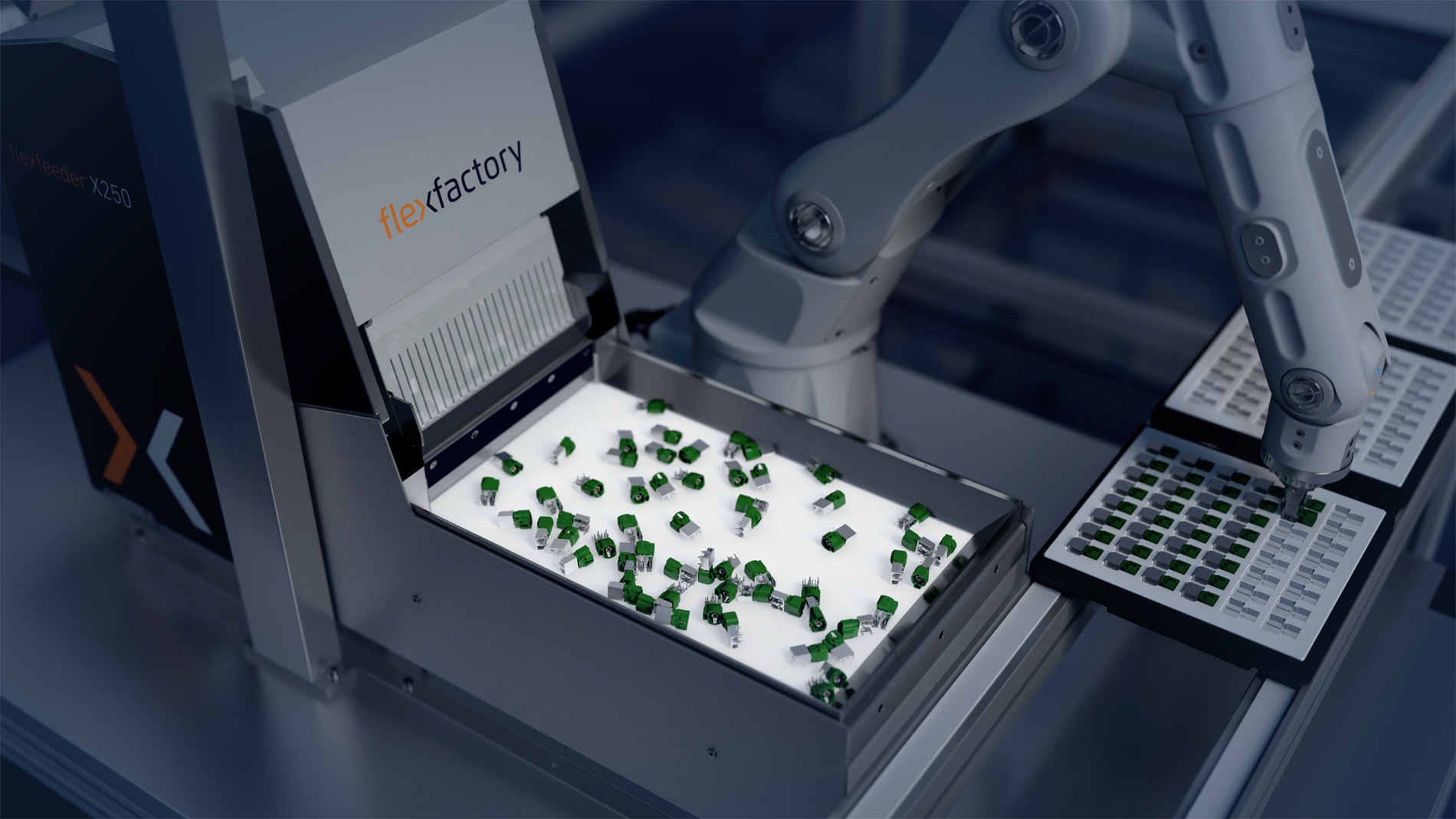
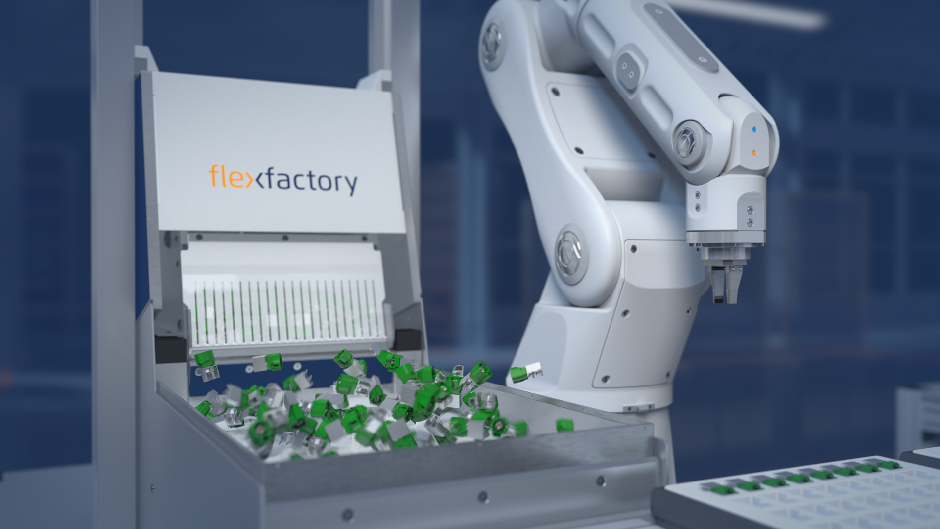
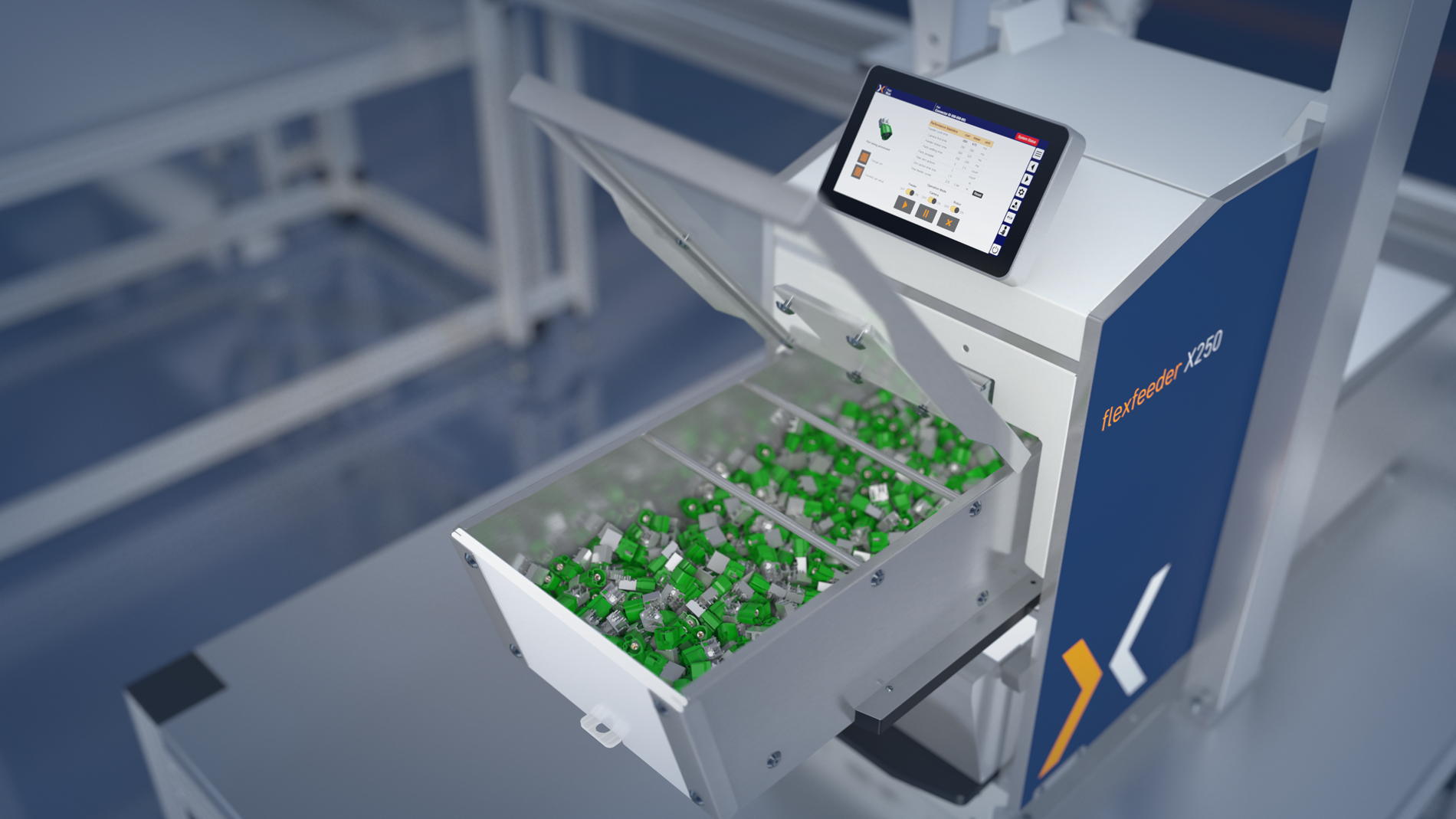
In a flexible feeding solution, the camera system is of absolutely central importance: The camera continuously analyzes the current situation on the feeder. It then decides which one of the many possible different movements of the feeder will lead to bringing the parts into the desired position. As many parts as possible and as quickly as possible. The feeder itself knows many different possible movements, and the camera decides in each case which of the possible movements is goal-directed. If the camera is then satisfied with the situation, it transfers the current coordinates of the identified parts to the connected robot. Several years of development have gone into the software on which our system is based. Compared to a car, you could say that the feeder’s camera-software-combination has the same role as the car’s engine – essential for operation and hard to replace. By the way, it’s important to know that even an absolute newcomer to flexible feeding technology can be trained on our system in only one day, and drivers for almost every industrial robot are now integrated in the system. There really is no easier and safer way to achieve success.
How can I find out whether and how well the parts I want to feed run on the flexfeeder?
This is actually the central question in every project. That's why we have set up a test center at our company and three employees are dedicated exclusively to performing tests for our customers. We usually carry out these tests with a robot, thus creating absolutely realistic conditions. After the test, each customer receives a detailed report of the test results, a video showing the feeding of the parts from different perspectives, and also a binding quotation for the components we recommend for this project and used in the test. In addition, we store all the software used in the test, which the customer then receives free of charge when purchasing a system. And should a product of the customer cause problems: We say it, we show it and we look for solutions together with the customer. We only really like to sell a system when we are convinced that the solution works as desired. This creates reliability on all sides!
Is there a basic rule as to what thesize of the flexfeeder should be in relation to the part size to be fed? How do I find the optimal flexfeeder for the application?
There is a rule of thumb for selecting the right flexfeeder:
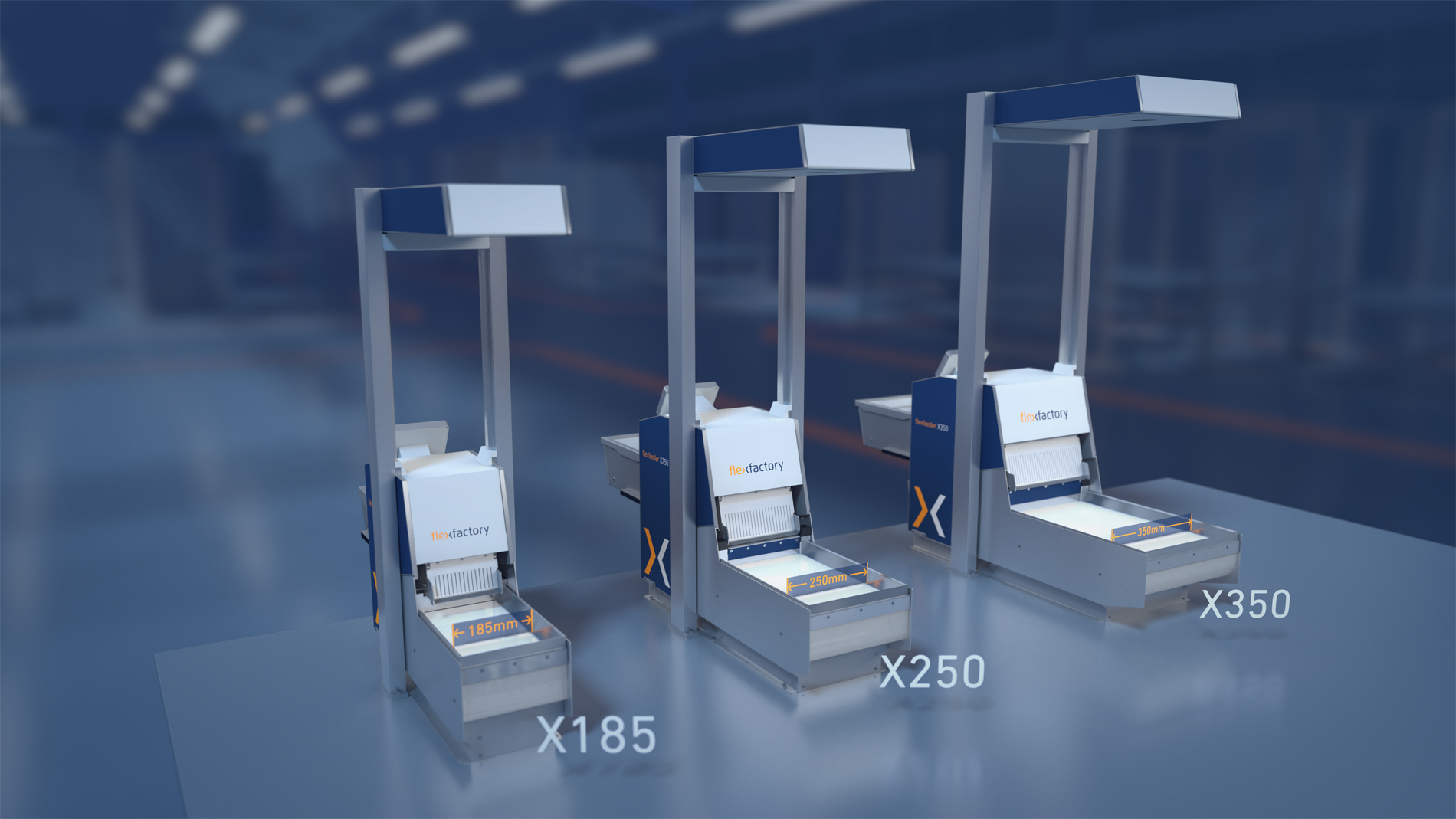
Feeder width = max. part length x 5.
As a rule, this formula works relatively well.
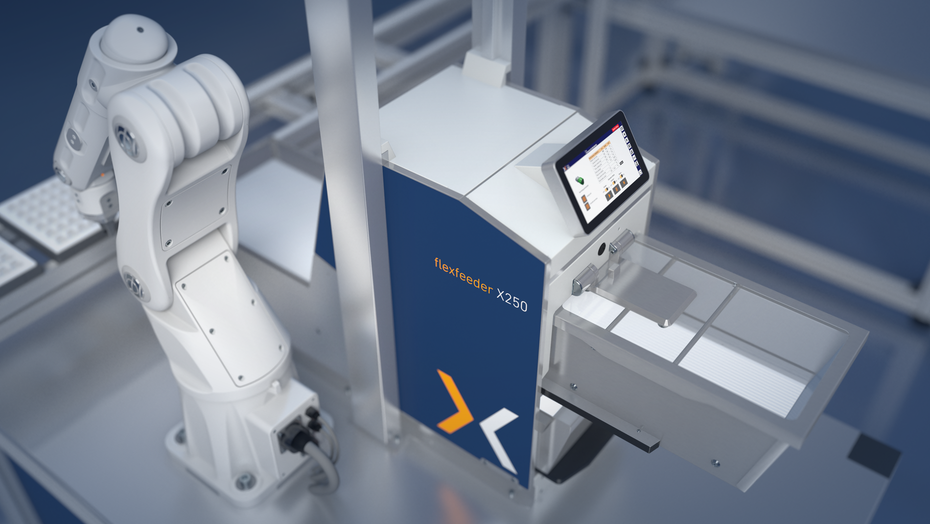
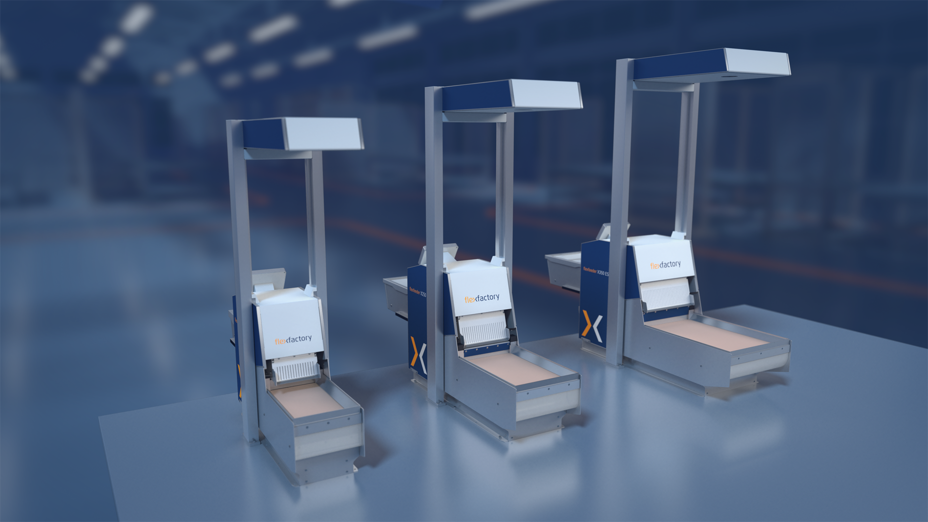
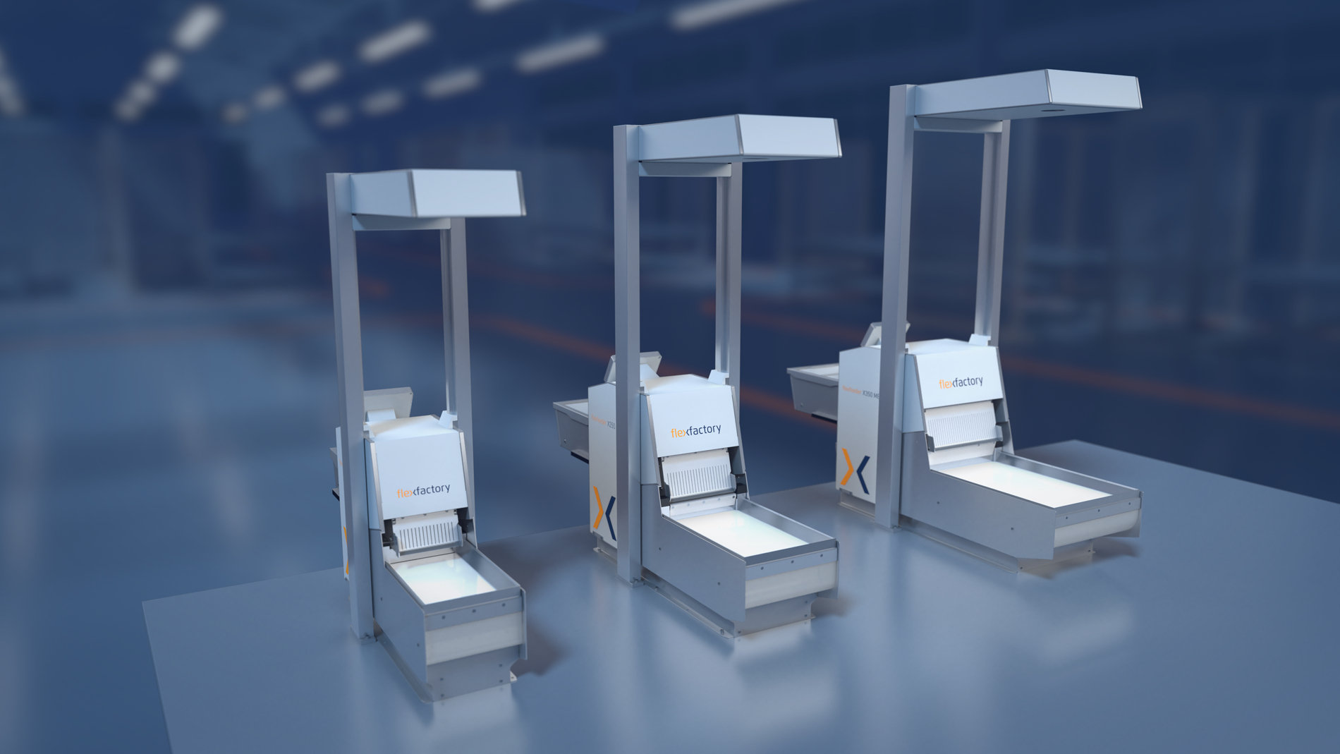
For example, if parts of 45 mm length are to be fed (45 x 5 = 225 mm), the flexfeeder X250 is the first choice. The number in the type designation of the flexfeeder indicates the width of the feeder.
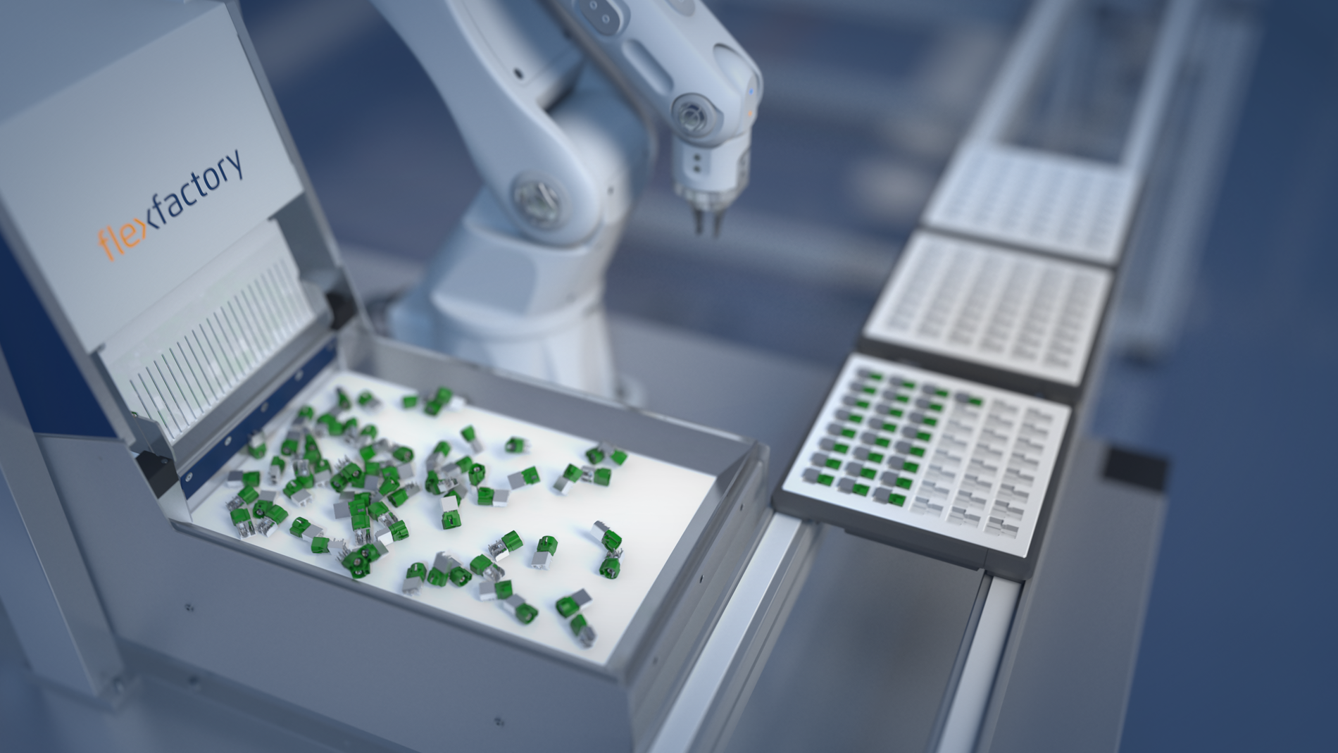
If you follow this rule of thumb, about 20 to 25 parts will fit into the image area of the camera and this leads to a good probability to always find some parts in the desired position. Usually, as the size of the feeder increases, so does the throughput within the application.
To get certainty, we perform tests with real parts on our feeders on request and thus determine the ideal configuration of each application.
At what distance and how do you install the camera with the flexfeeder?
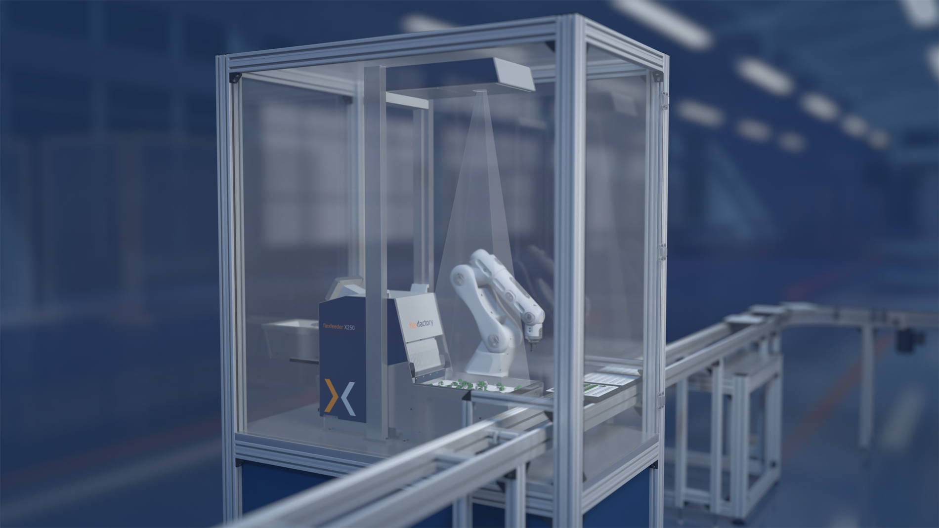
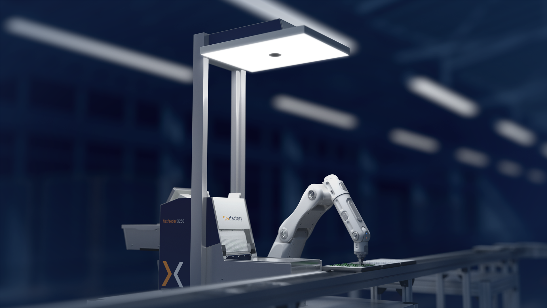
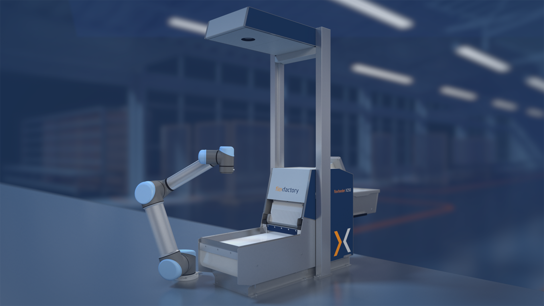
In each application, there is a predefined distance of the camera, which must also be strictly adhered to. The distance is defined by the resolution of the camera, the size of the image field and by the selected lens. A camera too close above the surface of the flexfeeder leads to distortions. Therefore, we deliver the flexfeeder with a completely preconfigured camera tower, which offers not only the camera but also a possibility to mount the optional toplight. Thus, everything is completely wired, which simplifies integration enormously and eliminates sources of error. This type of camera installation is particularly convenient when operating with collaborative robots without a protective enclosure, since there is no cell structure at all for mounting the camera and the toplight. The full integration of the camera and the toplight is a unique selling point of the flexfeeder series.
What happens to defective parts or accidentally wrong parts that are in the system?
In flexible feeding, "quality control" is quasi a free add-on.
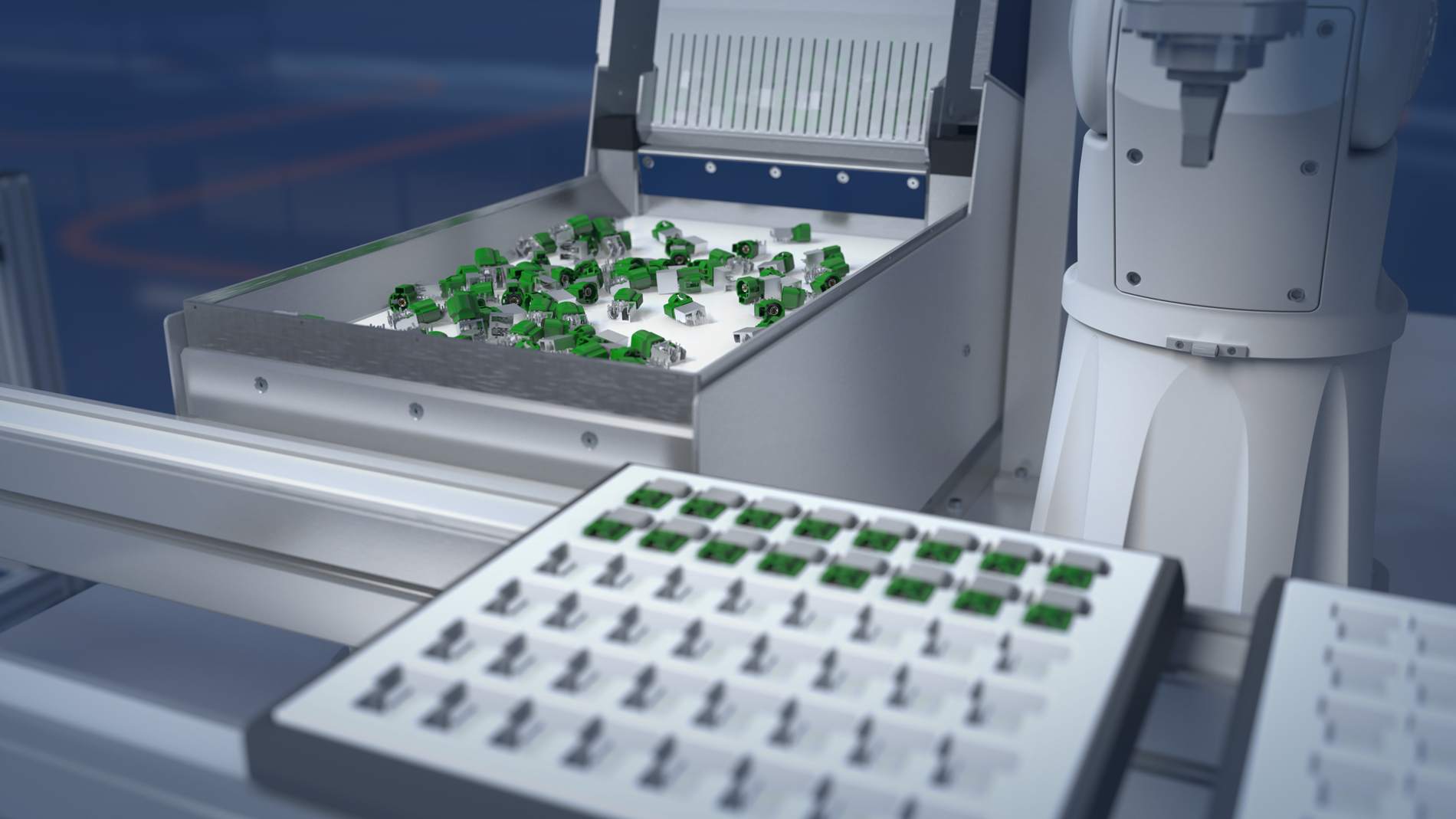
Unlike classic vibratory feeders, each individual part is measured here with the camera and compared with the stored reference model of the component. In the event of deviations from this model, the system flags these parts as faulty and prevents them from being removed by the robot. The specially integrated gate allows such parts to be ejected to the rear into an NiO box, especially if several of them have accumulated in the image area.
The flexfeeder system is thus self-destructing. A system standstill due to a faulty part, as is the case when using a traditional vibratory feeder, is not possible and faulty parts cannot be installed. This creates real process reliability through extremely high availability of the automation solution.
Is such a flexfeeder system reusable or is it always tailored to the specific application?
Just like an industrial robot, the flexfeeder is a reusable piece of equipment. With a flexfeeder X250, for example, parts can be fed in a range of 0.2 mm - 90 mm in length. The system is therefore optimal, especially for changing requirements and changing products. Many of the systems supplied by flexfactory have been in use for more than 10 years and are in operation with constantly changing components.
"Solving tomorrow's problems today" - this maxim is consistently implemented by using flexfactory's flexible feeding systems.
Is a feasibility study necessary in every case to determine whether and with which flexfeeder system an application is feasible?
Quite clearly: No! As a rule, all we need is a photo or a drawing of the parts to be fed with details of the desired position and the required throughput. Based on this, our specialists can identify the suitable system and the customer usually receives a budget offer for exactly this system within a few hours. However, the selected configuration should be verified by a test with real components, especially for critical parts and high throughput. This creates reliability and also often helps our customers to achieve acceptance for the solution.
What is the solution for rolling parts? Don't they move on the surface of the flexfeeder for a very long time?
The flexfeeder’s surface is constructed in a way that the flexfeeder plate (made of POM) can be exchanged completely without tools within a few seconds.
For parts that tend to roll, choose a structured plate. Many different plates are available for each flexfeeder. If necessary, customized plates can also be designed and manufactured.
In our tests, we determine the optimum plate for each component and document the behavior of the parts by video. In this way, we ensure that the requirements for the solutions are also guaranteed to be achieved or, in most cases, even exceeded.
How can I find out whether and to what extent there is potential for the use of flexible feeding technology in my company?
We will gladly come by for a visit. Together, we analyze the potential for this kind of application. We will show you the possibilities, but also the limits, and together with you we look for possible partners for the implementation of the task. In doing so, you will benefit from our large network in the world of automation technology. No matter whether you have questions about the gripper or need support in programming the application - we will either help you directly or establish the right contacts.
Our goal is long-term cooperation with our customers, and we can only achieve this if you are satisfied with us and our solutions.
Are there possibilities for remote maintenance of a flexfeeder application?
We are in close contact with many of our customers and, if required, we also have the means to access the solution online and make adjustments.
Our system is prepared for remote maintenance and quick help when problems occur is a matter of course for us. This also includes a completely free hotline and a two-year warranty on all systems supplied by us. In many cases, we also have customer parts in stock, so we can carry out optimizations and import the changed parameters directly into the customer's system. In this way, we create safe production conditions and also help to maintain them after delivery of the system.
How time-consuming is the training for such a system? Isn't it an application that is very complicated to realize?
Our goal is that our customers are able to master the system from A-Z,, to be able to commission it independently and also to maintain it. The ideal candidate for commissioning a camera-guided flexfeeder system is also the person who programs the robot.
After a training course of only a few hours, which we can also conduct on site if desired, every robot programmer is able to calibrate flexfeeder, camera and robot to each other, teach new parts, adjust the appropriate parameters for the flexfeeder's movements and establish communication with the robot. Due to the constantly growing number of robot drivers, the last point in particular is particularly easy to implement, regardless of which manufacturer the robot comes from. On-site know-how creates independence, reliability and satisfaction with the implemented solution, and this is exactly what we aim to achieve.

